BeeRotor F3 OSD NAZE32
840,00 TL + KDV
Stok Kodu
AEFPUX68
Fiyat
840,00 TL + KDV
KDV Dahil Fiyat
1.008,00 TL
Features
• Optimization for Cleanflight/Betaflight firmware
• ARM Cortex-M4 core STM32F303CC with 32bit/72MHz/256K Flash/40K SRAM and hardware floating point unit
• MPU6050 and BMP180 / BMP280 Sensors
• Build-in 8MB flash for black box log recorder
• On board OSD with absolutely original MAX7456EUI+ and standard FTDI debug port
• Receiver connector with PPM/SBUS/SumD/DSM2/DSMX and RSSI input
• Up to 3 serial ports and 8 PWM outputs
• Multifunction connectors with SWD/UART2~3/Soft-serial/Buzzer/LED trip/Voltage detection
• Multifunction OSD connectors with video_IN/ video_OUT/ICSP/debug port (UART1)
• PDB connector with 5V input/Current and Voltage detection
• Power input reverse polarity protection
Specification
• Power input: 5.0~5.5V
• Dimension: 35x35x9mm
• Fixing hole spacing: 30mm
• Weight: 7.3g
• PPM/RSSI/SBUS/SumD Receiver Cable
• Camera/video-TX cable
• Buzzer/LED strip/voltage detect cable
• OSD debug port to FTDI adapter cable
Getting started
First
• Install lastest Silicon Labs CP2102 USB to UART bridge VCP Driver.
http://www.silabs.com/products/mcu/pages/usbtouartbridgevcpdrivers.aspx
• Install and launch the Cleanflight Configurator tool.
https://chrome.google.com/webstore/detail/cleanflight-configurator/enacoimjcgeinfnnnpajinjgmkahmfgb
• Connect flight controller to computer via USB cable.
• Select the correct COM port if it is not automatically detected.
• Click connect, verify that communication is established.
Basic configuration
• Calibrate sensors
• Configure ports.
• Enable features.
• Configure receiver mode.
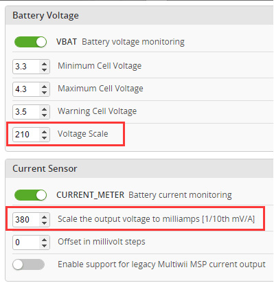
• Configure voltage monitoring. Voltage Scale must be 110.
• Configure current sensor. If you use BRPDB the Scale must be about 380.
• Configure RSSI if you using a receiver with RSSI output.
• Configure other features.
• Configure receiver, set channel mapping.
• Learn about flight modes and configure channels/switches to activate them as required.
• Learn how to arm/disarm.
• Bench-test failsafe.
• Read safety notes.
• Learn how to download and view your flight logs to help tune your aircraft.
• Erase dataflash contents before first flight (so you have a log).
• Learn how to recognise un-tuned flight characteristics and the effects of a PID controller. (Watch some videos).
• First flight should be in Acro/Rate mode (the default mode when no other modes are active).
• Tune PIDs.
• Backup settings.
Firmware Flash (upgrade)
• Disconnect power, USB cable and click the Firmware Flasher tab.
• Click load Firmware [local] and found that the firmware file.
• Be sure selected No reboot sequence / Full chip erase / Manual baud rate 25600.
• Press and hold the boot button and released after connecting the USB cable.
• Click Flash Firmware and wait for the prompts to complete it.
OSD debug
• Don’t connect any power to the quad.
• Install FT232 VCP driver and connect FTDI to SE port via FTDI adapter cable.
• Download MWOSD GUI zip file and open it.
• Select the right COM port and wait for reading OSD configuration parameters.
• Learn how to modify the parameters, font and write back to the mcu of OSD.
Jack and power distribution
• The 328P of OSD connected to F303 via UART1.
• GPS/SWD/I2C jack connected to F303 via UART2.
• SBUS/DSM2 jack connected to F303 via UART3.
• When using PDB or external 5V power supply, OSD circuit keep working and communicate with the F303. If you plug a
USB cable, the OSD circuit is cut off powered to ensure that the FC can communicate with computer.
• When debugging OSD, do not connect the battery/USB cable and just plug a FTDI tool via the FTDI adapter cable. At this
time only OSD circuit to work independently


Bu ürüne ilk yorumu siz yapın!


